 Deutsch
 English
 Francais
CMS
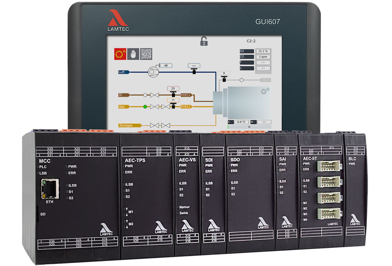
Combustion Management System


CMS Combustion Management System
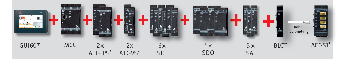
- Modular combustion management
- Suitable for simple to high-end applications
- Inputs/outputs freely configurable
- Largely language-neutral due to use of symbols
- Worldwide approval CE/UL/SIL 3
- CODESYS Soft-PLC integrated
- Integrated fault indicatior system
- Modbus TCP on-board
- O2 control
- Adaptive CO/H2 combustion optimisation (SIL2)
- Integrated flame monitoring
- Integrated valve leakage test (VLT)
CMS - The next evolutionary step in combustion management
Whether standard industrial combustion or more complex process applications, the revolutionary LAMTEC CMS burner and plant management system sets new standards.
Modular: The CMS can be easily adapted to the needs of the plant. From small industrial burners to large plants, everything can be controlled.
Safe: The modules are connected via the fail-safe iLSB.
Communicative: The CMS has a Modbus TCP interface as standard. Other fieldbus modules can be connected, e.g. PROFIBUS DP, PROFINET, Modbus RTU in preparation.
Simple: The CMS supports graphic and intuitive user guidance.
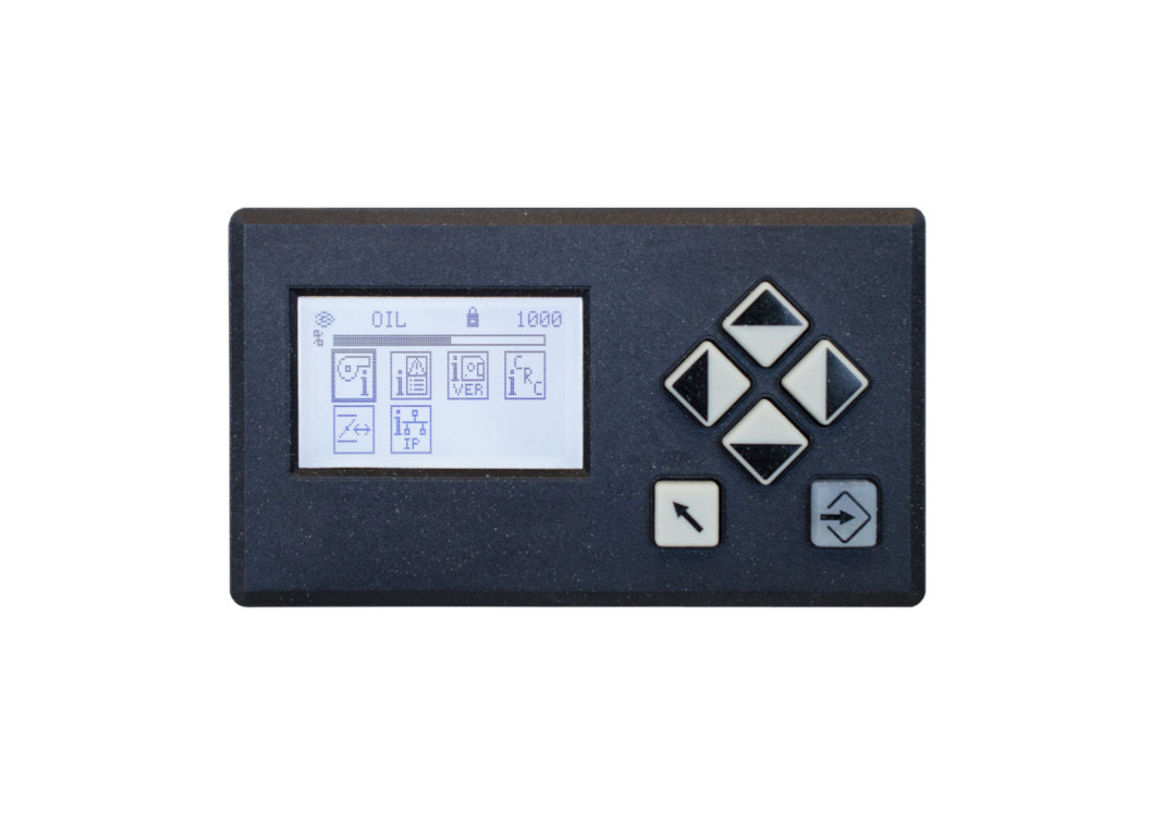
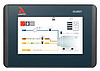
Demand-oriented: Whether simple and cost-effective UI400 user interface or 7" colour touch screen (GUI607) for more comfort - with the LAMTEC CMS you are not limited in visual output.
Versatile: Integrated soft PLC (CODESYS) for non-failsafe control tasks.
Flexible: Free assignment of burner functions to inputs and outputs in the CMS.
| Technical Data |
|
||||
| Approvals |
EC Type Examination Certificate according to 2014/68/EU (Pressure Equipment Directive)
EC Type Examination Certificate according to 2016/426/EU (Gas Appliances Regulation)
SIL 3
CE Declaration of Conformity
USA and Canada
|
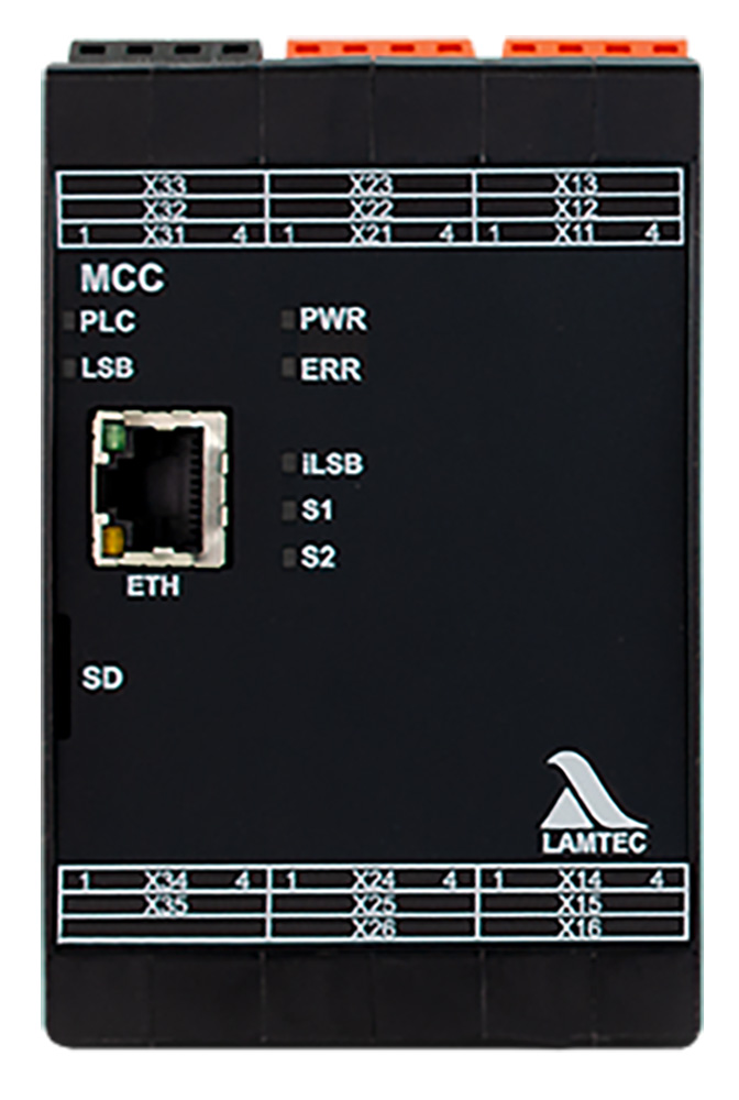
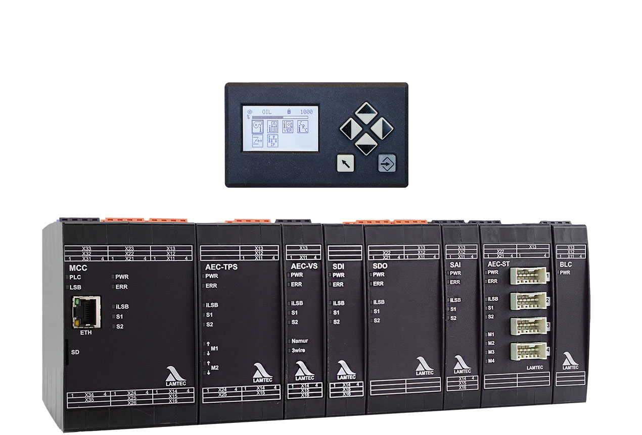
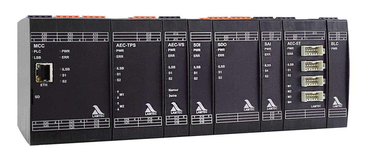
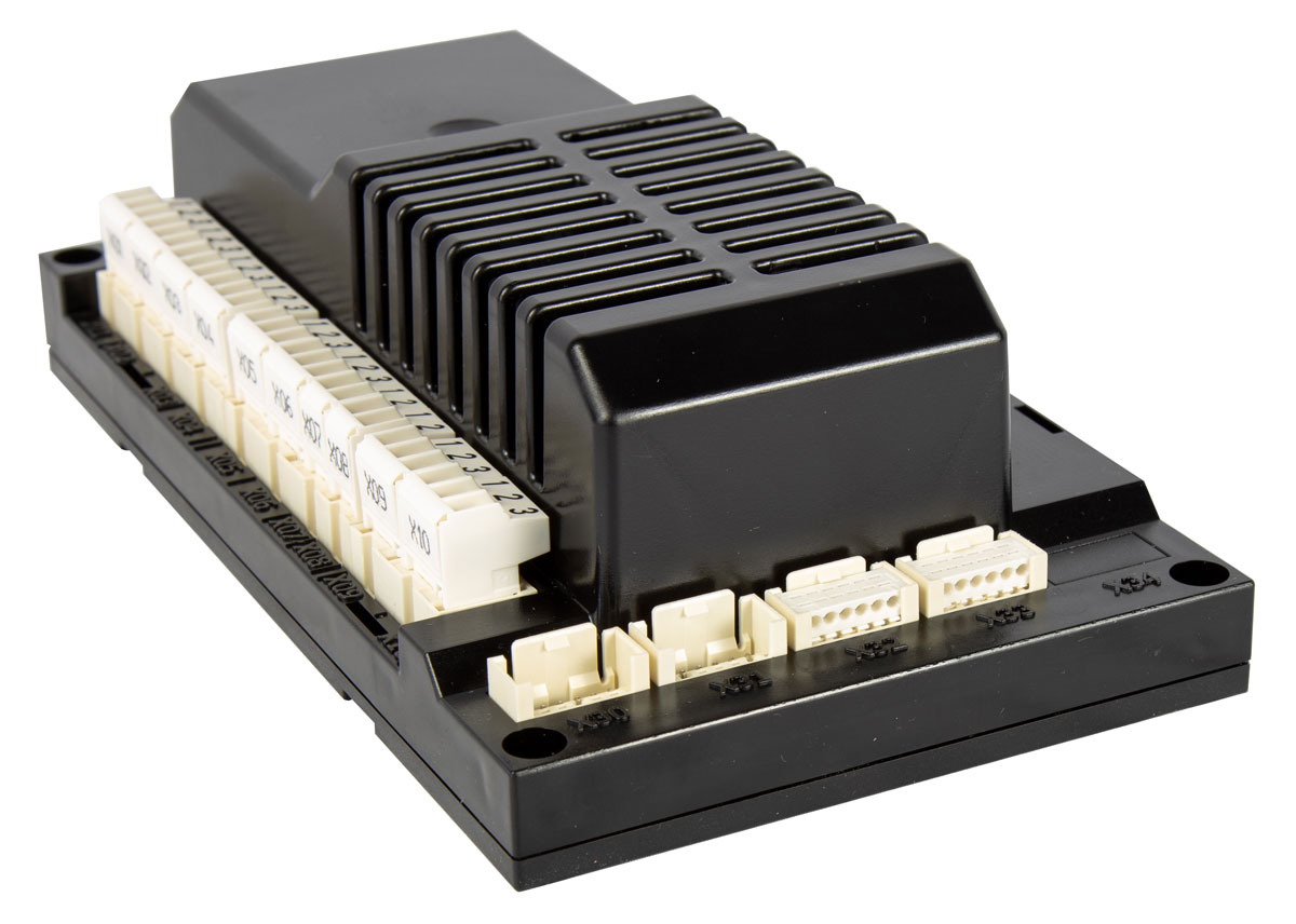
MCC
Your advantages at a glance:
- Burner sequencer
- 12 Digital Inputs, 9 digital Outputs, freely configurable
- 2 A per output, max. 8 A in total
- Input for flame sensor FFS07/08 (option)
- Input for ionisation (option)
- Firing rate input 4-20 mA/TPS or potentiometer,
Output 4-20 mA internal firing rate - CODESYS Soft PLC with access to internal variables for non-failsafe extensions
- ModbusTCP interface on-board (Ethernet)
- Versions available:
- Input 230VAC | Output 230VAC
- Input 120VAC | Output 120VAC
- Input 24VDC | Output 230VAC
- Input 24VDC | Output 120VAC
- Input 24VDC | Output 24VDC

AEC-TPS
Your advantages at a glance:
- 1 Module supports 2 TPS actuators
- Current output supports up to 0,5 A per actuator
- Up to 5 AEC-TPS modules per system
- CMS actuator available from 6 Nm to 200 Nm
- Technically compatible with ETAMATIC/FMS actuators (type approval has to be checked)
- Up to 10 actuators per CMS system possible
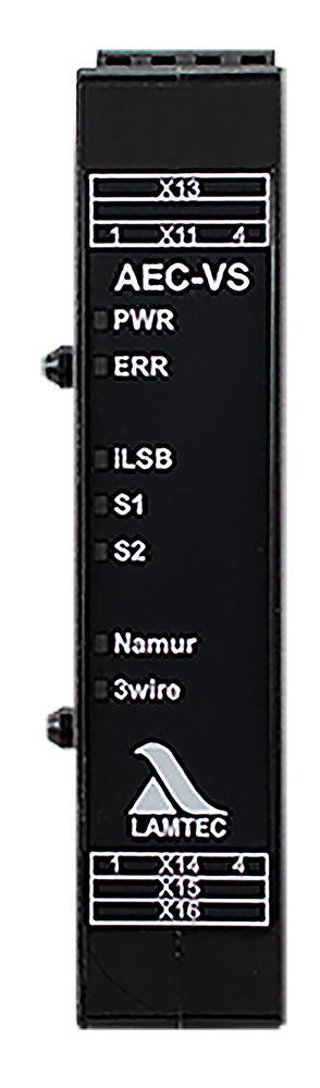
AEC-VS
Your advantages at a glance:
- Module for frequency inverter of the combustion air fan or recirculation fan
- Module for 4-20 mA motors, pneumatic actuators etc.
- Up to 10 AEC-VS per CMS system possible
- VSD module with feedback input for:
- Namur sensor
- 3-wire sensor
- 4-20 mA - Floating digital output (freely configurable for non-failsafe output, e.g. fan ON signal)
- Digital input (freely configurable for non-failsafe default, e.g. fault VSD)
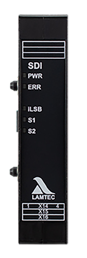
SDI
Your advantages at a glance:
- 8 digital Inputs per module
- All inputs are freely configurable
- Available in alternative versions for 115/230 V and 24 VDC
- Up to 6 digital input modules
- Up to 60 digital inputs possible per CMS system.
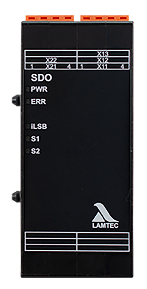
SDO
Your advantages at a glance:
- 8 fail-safe outputs per module
- All outputsarefreelyconfigurable
- Available in alternative versions for 115/230 VAC and 24 VDC
- Up to 4 digital output modules per CMS system
- Up to 41 digital outputs per CMS system possible
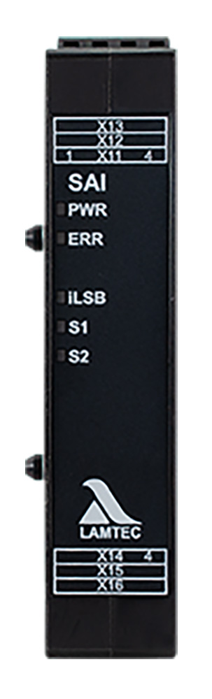
SAI
Your advantages at a glance:
- 3 failsafe analogue inputs, or 6 non-failsafe analogue inputs, or any combination possible
- All inputs are freely configurable to the functions
- Inputs: 4-20 mA, 0-10 V impulse or digital
- Up to 3 SAI per system
- Up to 9 failsafe or 18 non-failsafe inputs per CMS system possible
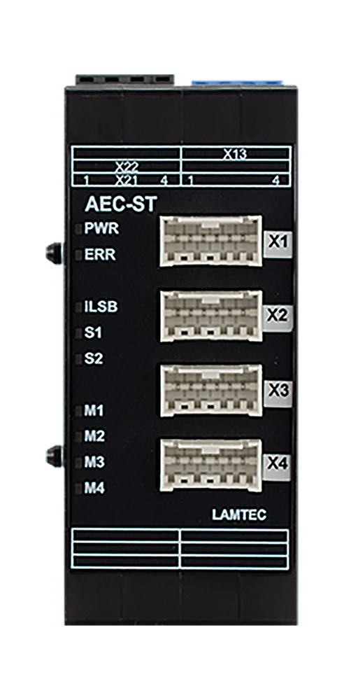
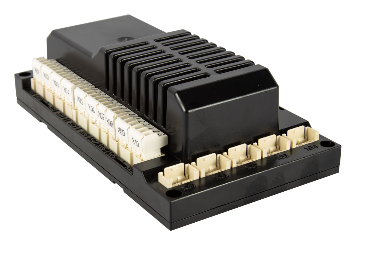
AEC-ST
Your advantages at a glance:
- Compatible to the stepper motors of the BT300
- 1 Module supports 4 stepper motors
- 0,8 Nm, 1,2 Nm, 3 Nm, 9 Nm
- 2 AEC-ST Modules per CMS system
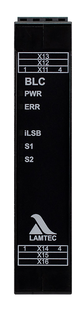
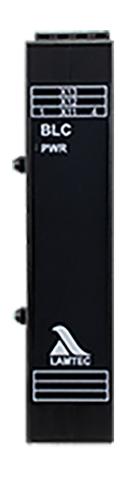
BLC
Your advantages at a glance:
- Connecting CMS modules installed at different locations
- Modules for extending the CMS internal bus via cable
- Maximum length of a bus segment 70 m
- BLC Active:
- Always located at the end of a bus connection (receiver module).
- Opens a new bus segment for the modules connected thereafter for bus lengths > 70 m
- Requires active +24V DC power supply.
- BLC Passive:
- Always located at the beginning of a bus connection (transmitter module).
- Can also be located at the end of a bus connection (receiver module). In this case, no new bus segment is started.
- Does not require a separate +24V DC power supply.
| BLC active | BLC passive |
|  |
- Displays
- Display UI400
- Cover IP65 for UI400
- Colour display with GUI6xx touch panel - Bus modules
- PROFIBUS module 668R1400
- PROFINET module EBM412 - Remote Software
- CMS Remote Software for configuring the CMS system - Dampers
- Gas dampers
- Air dampers
- Flue gas dampers
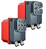
The dampers can be mounted on our actuators on request. - Actuators
- Actuator 668M20xx
- Actuator 662R5X - Measuring systems
- O2 measurement for O2 trim e.g. LT3/LS2
- O2 measurement/COe detection for CO/H2 control e.g. LT3-F/KS1D - Flame monitoring system
- Flame sensor
•FFS07/FFS08
- Flame scanner
• F200K and F300K - Power Supplies
- 100 ... 240 VAC/24 VDC, 15 W - 150 W power supply unit for voltage supply to the CMS
You can find additional accessories in the product catalogue.
Accessories available via our sales representatives
Direct connection
- Flame Scanner FFS07 / FFS08
- Ionization electrode (230 V CMS, not included in the LAMTEC portfolio)
- UV tube, strictly for intermittent operation (in progress)
Connection via digital input
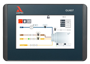
- Touchscreen
- Available in various sizes (7“ GUI607, 10“ GUI610, 15“ GUI615)
- Graphical user interface (GUI)
- Largely language-neutral
- Plant image
- Option to save backup record
- Customizable graphics according to customer specifications
- Setup assistant
- Unlimited distance to MCC (Ethernet)
- Integrated CODESYS PLC for customer-specific functions

- Cost-effective User Interface
- Graphical user interface
- Language-neutral display
- Easy to use
- Connection via LAMTEC SYSTEM BUS (LSB)
- up to 500 m distance to MCC
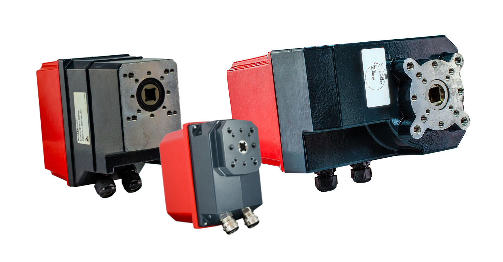
CMS actuators from TPS06 to TPS200
- from 6Nm to 200Nm
- Max 10 actuators per CMS
- 6-40Nm TÜV-certificated for use with the CMS
- 60-200Nm individual approval

662R5X actuators (only in combination with AEC-ST module)
- from 0.8 Nm to 9 Nm
- Max. 4 actuators per module
- TÜV-certificated for use with CMS AEC-ST module and BT300
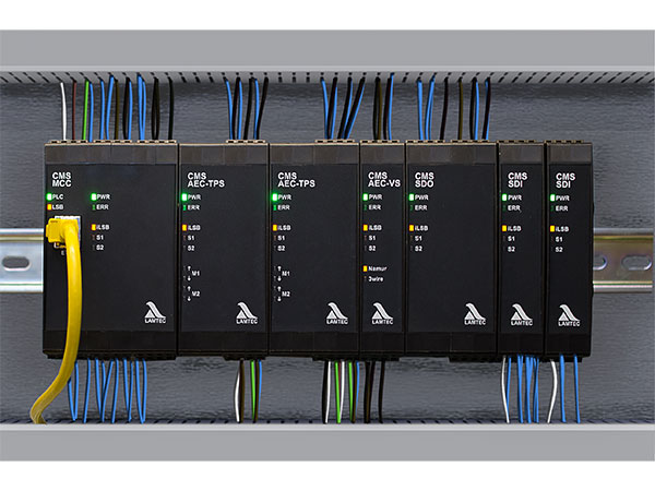
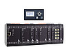
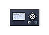
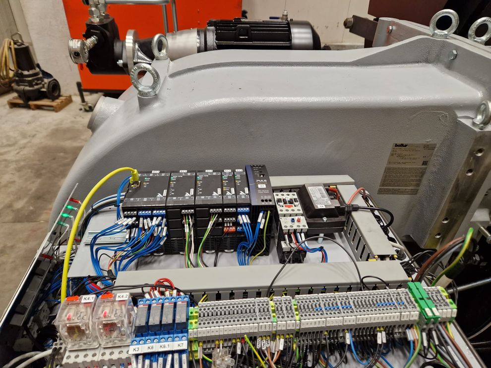
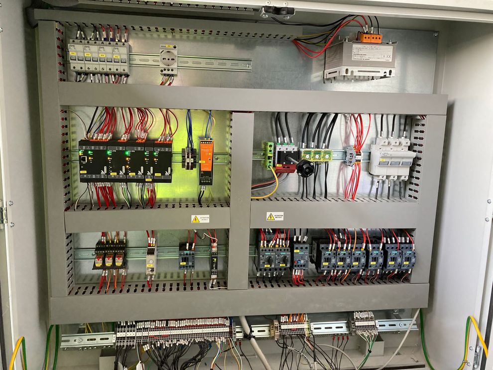
CMS on burner | CMS in control cabinet |
 |  |
Further downloads can be found in the support section .
All products in this category
CMS
Combustion Made Simple - Whether standard industrial combustions or more complex process applications, the Combustion Management System CMS can be easily adapted to the needs of your facility.
BurnerTronic BT300
The burner control system BurnerTronic BT300 combines the advantages of an electronic fuel/air ratio control with an electronic burner control unit. With the help of the BT300, standard applications are easily configured.
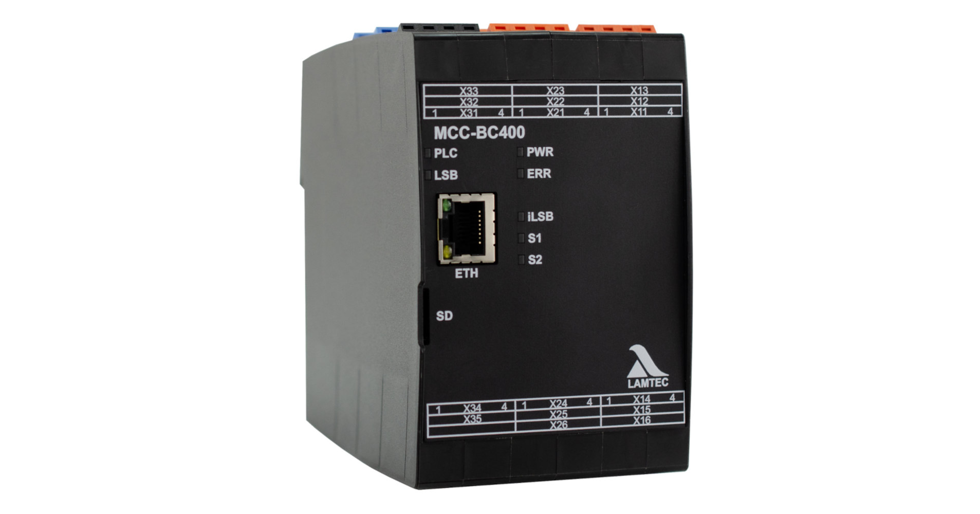
BurnerControl MCC-BC400
MCC-BC400 is a burner control for oil, gas, and dual-fuel burners. It controls and monitors burners of unlimited capacity in both intermittent and continous operation.
BurnerControl BC300
BurnerControl BC300 is a gas burner control for industrial burners on thermal process plants. It is designed for use on burners of all sizes in intermittent and continuous operation.
Other well-proven burner control systems
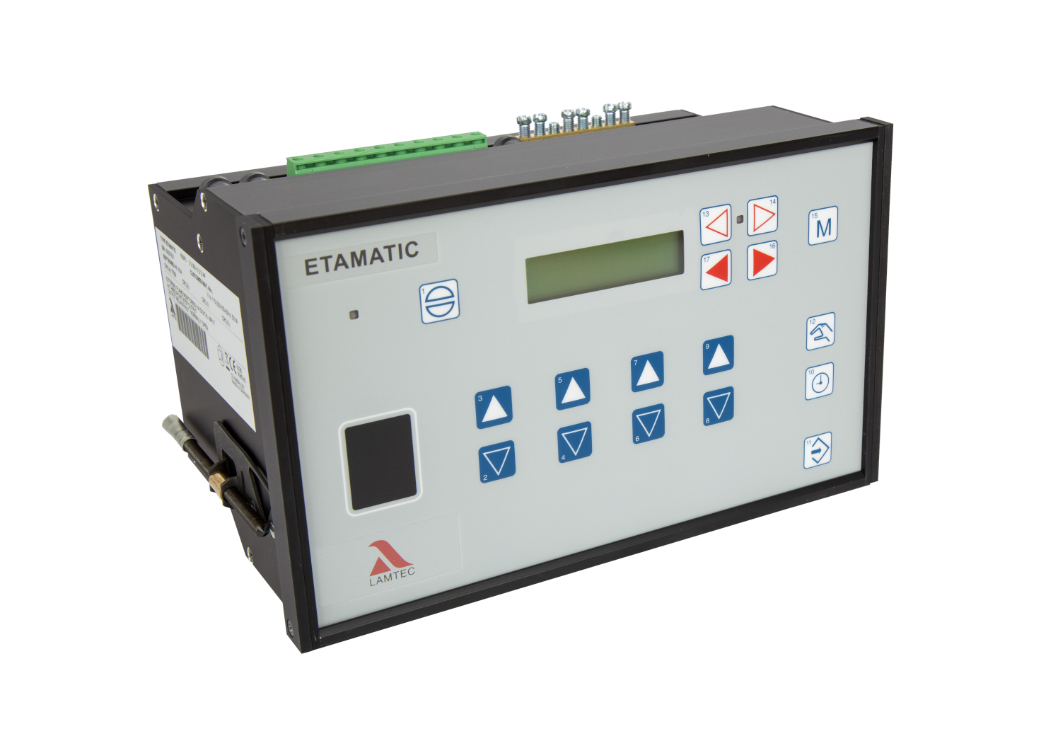
Compact multifunctional solutions such as our ETAMATIC, FMS and VMS not only impress with their user-friendly commissioning, but also score points with their integrated CO/H2 control, failure safety and durability.